|
|
|
|||
        |
|
|
|
[an error occurred while processing this directive]
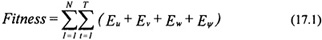
In most problems involving a genetic algorithm search, there is a performance versus time issue involved; performance generally improves as the number of possibilities considered increases — a move that obviously increases the time required to complete the search. The complexity (computational intensity) involved with the fitness function is the major factor in the time required to compute a solution. Here, the fitness function is composed of a weighted sum of differences. The difference between a set of states and their desired values is calculated as error at each time step. The absolute values of the errors are summed over the course of the simulation yielding a cumulative error for each of the states. These cumulative errors are combined in a weighted sum to produce the fitness. In the helicopter problem, the fitness value typically consists of a weighted sum of integrations of state error over several simulations. Several simulations with different initial conditions and goals were needed to adequately cover the parameter space being searched on see discussion in Chapter 3 on the cart-pole controller). A typical fitness function for N separate simulations lasting T seconds is defined as:
where Eu is the error in the forward velocity, Ev is the error in the rightward velocity, Ew is the error in the downward velocity, and EΨ is the error in the reference heading. Since the fitness function in this problem is so computationally intensive, the genetic algorithm was applied in distinct stages to search for the fuzzy rules. In the first stage, the genetic algorithm was employed to search the entire parameter space for a solution that was not immediately divergent. In this stage, the only region of flight considered was hover. In the second stage, each section of the controller was trained independently. First, all rules except those in the Longitudinal Attitude block were excluded from the search. The Longitudinal Attitude block was trained using a fitness function that evaluated short simulations from several sets of initial conditions to various attitude goals. In this way, the control block was trained to reach and maintain a desired pitch angle. Next, the rules for the Longitudinal Hold block were discovered. The fitness function consisted of several simulations at different airspeeds. The criteria for evaluating quality performance was based on how well the controller could maintain airspeed despite perturbations. At this point, the controller could maintain forward airspeed. The next step was to train the Longitudinal Acceleration block to allow airspeed changes. Once again, the fitness function entailed several simulations in which the controller was required to accelerate and decelerate the helicopter through a range of airspeeds. This procedure was repeated for the other three sections of the controller. A few iterations of this process were required to achieve good performance throughout the flight envelope. It is important to note that the training of the fuzzy controller was not accomplished on a personal computer. To solve this problem in a timely manner, the genetic algorithm was implemented on a network of approximately 40 workstations. Even then, the design of the controller took on the order of a week to complete. 17.6 ResultsThe helicopter fuzzy logic controller was developed to perform several maneuvers throughout the flight envelope of the UH-1H helicopter. Effective rules for the fuzzy controller were discovered using a genetic algorithm and a numerical model of a UH-1H helicopter. The performance of the controller was evaluated both in simulation and in actual flight tests conducted at White Sands Missile Base in conjunction with the U.S. Army. Its successful performance in controlling the model indicates the effectiveness of a genetic algorithm in generating fuzzy logic rules. Figure 17.5 shows the results of the controller performing a simulated hover. In this figure, u, v, and w are the forward, rightward, and downward velocities of the helicopter measured in meters per second, respectively. The heading (Ψ) is measured in degrees. After a brief period of transition, the controller brings all velocities and the heading to zero.
Figure 17.6 shows data for a transition from hover to 5 m/s forward taxi. The heading and lateral and vertical velocities are held near zero. In forward flight, a coordinated turn is performed by flying the helicopter to a new bearing without allowing lateral velocity. Figure 17.7 shows data for a coordinated turn at 34 m/s forward airspeed. The airspeed is maintained through a right turn of 60 degrees. Climb rate is held at zero for the duration of the turn. There is, however, oscillation in the lateral velocity. This is a result of a flaw in the controller design. The pedals are used to control heading at hover, but need not be used in forward flight except to trim the aircraft during transition to forward flight. The Lateral Trim control block in the helicopter fuzzy controller constantly tries to correct lateral velocity errors in forward flight using the pedals. The fuzzy controller should be redesigned to provide trim during transition only.
Since the fuzzy logic controller performed well in simulation, it was used in an actual flight test. Because there are differences between the dynamics represented by the numerical model and the dynamics of the actual aircraft, the successful performance of the fuzzy controller on the aircraft in actual flight tests indicates the robustness of fuzzy logic used for flight control. Figure 17.8 shows the controller performing a hover in actual flight. It successfully holds all velocities and heading about zero for 90 seconds.
Copyright © CRC Press LLC
|
 |
         |
|
)
)
)
)