|
|
 |
[an error occurred while processing this directive]
17.3 The Helicopter
Th research effort described in this chapter focuses on the design of a control system for a UH-1H helicopter, sometimes called a “Huey.” Initial efforts are focused on testing a fuzzy control system on a simulation of the helicopter. However, the control system is eventually flight tested on an actual aircraft. The control system software was designed using a simulator developed at NASA Ames Research Center. The simulator is a nonlinear, total force and moment model of a single main rotor helicopter. The model has ten degrees of freedom: six for rigid-body dynamics, three for rotor-flapping, and one for the rotation of the rotor (Talbot, Tingling, Decker, and Chen, 1982). The simulator was modified at the Georgia Institute of Technology to specifically model the UH-1H, and to provide a simple interface to the control software and search algorithm (a genetic algorithm) used in this research (Mittal and Prassad, 1994; Patterson, 1994).
The state variables of an aircraft are generally defined about a right-handed aircraft body coordinate system with the x-axis pointing out the nose, the y-axis pointing out the right side, and the z-axis pointing out the bottom. From this convention, the following state variables are defined:
| u = dx/dt (m/sec)
| Forward velocity
|
| v = dy/dt (m/sec)
| Rightward velocity
|
| w = dz/dt (m/sec)
| Downward velocity
|
| du/dt (m/sec2)
| Forward acceleration
|
| dv/dt (m/sec2)
| Rightward acceleration
|
| dw/dt (m/sec2)
| Downward acceleration
|
| p (deg/sec)
| Angular velocity around the x axis
|
| q (deg/sec)
| Angular velocity around the y axis
|
| r (deg/sec)
| Angular velocity around the z axis
|
| Ru (m/sec)
| Reference (or desired) forward velocity
|
| Rv (m/sec)
| Reference rightward velocity
|
| Rw (m/sec)
| Reference downward velocity
|
| RΨ (deg)
| Reference heading
|
Aside from the variables defined in body coordinates, the yaw, pitch and roll angles are defined as Euler angles in a ground reference frame. Obviously altitude is also defined with respect to the ground reference frame. Notice that all distances are measured in meters, all angles in degrees, and time in seconds. Therefore, aside from the variables introduced above, the following variables are important in this particular problem
| Ψ (deg)
| Yaw (heading)
|
| Θ(deg)
| Pitch (angle from horizon to the nose)
|
| Φ (deg)
| Roll (angle from horizon to the right wing)
|
| h (m)
| Altitude
|
17.4 Fuzzy Logic Controller Architecture
The goal of the effort described here is, first and foremost, to develop a control system for a helicopter. But, above and beyond that, the goal is to develop a system that is aggressively effective, computationally efficient, and easily adaptable to new rotorcraft. Furthermore, it is desirable to have the system perform as well as a human pilot. To achieve these goals, the controller must be capable of quickly and smoothly moving the helicopter from one steady state condition to another. It must also be able to perform a simple set of maneuvers such as acceleration, deceleration, and steady turn. As with any computational system, the simpler the algorithm that accomplishes the specified tasks, the better.
Fuzzy control directly addresses many of the concerns associated with the above stated goals. In the end analysis, it is the specific architecture of the controller that determines the success or failure of the controller in achieving the goals set forth. The controller architecture will also determine the way state information flows through the controller. In the systems we have dealt with to this point in the book, the state variables were always related to the extent that we could not manipulate any information independently. However, it is important to note that information that is unrelated, or not greatly coupled, can be sent to separate processing blocks, termed “fuzzy blocks.” Using such an approach accomplishes at least two things. First, this approach allows a controller to be developed that has specialized sections. Each section deals with a unique portion of the state space and addresses a specific aspect of control. Second, this approach substantially reduces the number of rules required by the fuzzy controller.
A classical fuzzy controller would typically consists of one fuzzy block with an input for each state variable (xi) and an output for each control action (yj) as shown in Figure 17.3a. In this architecture, each input variable is explicitly related to the other input variables through rules in the rule base. This classical fuzzy control architecture is the one we have developed in all fuzzy systems descried to this point in the book. For large problems, however, the classical approach to the development of fuzzy systems becomes impractical because the number of rules increases multiplicatively with the number of input variables. If each of the 17 variables used in the helicopter controller were described with but three membership functions, then the rule base would contain 317 (approximately 129 × 106) rules. A fuzzy controller with a rule set of this size would be terribly slow.
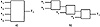
Figure 17.3 A classical fuzzy controller (a) can often be replaced by a modular architecture (b) that performs adequately.
|


)