|
|
 |
[an error occurred while processing this directive]
13.2 Problem Environment
The environment used as a vehicle for introducing the three component architecture is a laboratory pH system that is a small-scale representative of pH systems present in a number of industries (Kelly and Spottiswood, 1982; McAvoy, Hsu, and Lowenthal, 1972). The goal of the control system is to drive the pH of a particular solution to a setpoint. The pH system contains nonlinearities and changing process dynamics, and is an extension of a system studied by Galluzzo and co-workers (1991). The nonlinearities occur because the output of pH sensors is proportional to the logarithm of hydrogen ion concentration. The changing process dynamic has three separate causes. First, there is a mechanism for introducing a buffer to alter the manner in which the pH responds as acid or base is added. (The addition of buffer is roughly analogous to increasing the inertia in a mechanical system.) Second, the concentrations of the acid and base that the controller uses to manipulate the pH of the system can be altered. Third, the setpoint of the system, the desired value to which the system pH is to be driven, can be altered.
A schematic of this pH system is shown in Figure 13.1. A beaker initially contains a given volume of a solution having some known pH. There are five valved input streams into the beaker. Only the valves controlling the two input control streams can be adjusted by the controller. The concentration of these two control input streams is changed by some “random agent” to be either 0.1 M HCl or 0.05 M HCl and 0.1 M NaOH or 0.05 M NaOH. The valves on the other three input streams are used to manipulate external streams or flows that are altered by the same random agent that manipulates the concentration of the control input streams. Thus, the problem environment can be manipulated by the control system, or by an external agent. Certainly, the control system must be able to control the problem environment despite the changes made by the external agent. Furthermore, the control system has no knowledge of the changes being made by the external agent. Of the three uncontrolled external streams, one is 0.05 M HCl, one is 0.05 M CH3COONa, and one is a buffer (a combination of 0.1 M CH3COOH and 0.1 M CH3COONa). Additionally, the random agent is capable of changing the desired setpoint to which the system pH is to be driven.
The random agent allows for alterations in the system parameters that dramatically change the way in which the problem environment reacts when adjustments are made to the valves on the control streams. Furthermore, the control element has no knowledge of the changes made in the concentrations of the control input streams by the random agent; it is left up to the analysis element to recognize that the concentrations have changed, and to determine what the new concentrations are.
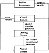
Figure 13.1 The pH system shown above is a challenging system to control. Aside from the nonlinear nature of pH, the control system is faced with changing conditions including the possible buffering of the system.
The goal of the control problem is to drive the system pH to the desired setpoint in the shortest time possible by adjusting the valves on the two control input streams. Furthermore, the valves on the input streams must be fully closed at the setpoint. As a constraint on the control action, the valves can only be adjusted a limited amount (0.5 mL/s/s, which is 20 pct of the maximum flow rate of 2.5 mL/s), thereby restricting pressure transients in the associated pumping systems.
The pH system was small so that experiments could be performed in limited laboratory space. Titrations were performed in a 1,000-mL beaker using a magnetic bar to stir the solution. Computer-driven peristaltic pumps were used for the five input streams. An industrial pH electrode and transmitter sent signals through an analog-to-digital board to a 33-MHz 386 personal computer that implemented the control system.
|


)